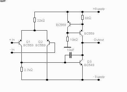
Figure 1 - Discrete Op-Amp

| Elliott Sound Products | Project 07 |
It seems that the poor old op-amp is a device that everyone loves to hate, even the really nice ones that come from Burr-Brown (now Texas Instruments) and Analog Devices.
NOTE: The circuit presented is experimental, and should provide some fun to build and play about with. It has been built and tested, and works very well indeed. Please note that it is a low current Class-A opamp, and is incapable of driving low impedances. The minimum recommended load impedance is about 1k.

Figure 1 - Discrete Op-Amp
It has the advantage of a Class-A output stage, so there is no possibility of crossover distortion, and in the version shown, (my simulator tells me that...) using transistors with a gain of 100, the final circuit has an open loop gain of 690,000. The Class-A output runs at a current of 11mA, and the circuit should work fine with supply voltages from +/-12 up to +/-20 or more (depending on the voltage rating of the transistors).
The circuit shown was both tested and simulated with +/-20V supplies, and different supply voltages (as well as variations in the transistor characteristics) will require that the value of the 2.7k resistor (between base and emitter of Q3) will need to be changed to minimise DC offset. This also ensures that the collector currents in the LTP are equal, maximising gain and minimising distortion. A multi-turn trimpot can be used here to set DC offset to 0V.
The frequency stabilisation capacitor will need to be selected based on the closed loop gain - in some cases it won't be needed at all (but unless you have decent test equipment to verify that the circuit is stable, leave it in). Be very careful if the load is capacitive (or worse, a resonant circuit, such as coaxial cable) - the circuit will almost certainly oscillate. If this happens, use a 100 ohm "stopper" resistor at the output - after the feedback return - otherwise it will do no good at all.
Also, since the circuit is an opamp, it needs to have feedback resistors and a DC return path for the +ve input - just like any other opamp. Performance is very good with gains of up to 10 (perhaps more depending on what you want to use it for), and it can be made to have very wide bandwidth.
Suggested transistors (these are cheap, easy to get, and pretty good, too):
However good this may look, I can safely assure the reader that it doesn't even come close to something like the NE5532 dual op-amp, and it draws a lot more current, too. However, it is an interesting circuit to fool about with, and should actually give a good account of itself in traditional op-amp circuits.
One word of warning - the input impedance and bias current are much worse than even the poor old 741, but bandwidth, noise and distortion can be expected to be much better. Just don't try to use it with really high impedance circuits, and don't expect the output to provide the +/- 20mA or so you are used to, 'cause it won't.
| Copyright Notice. This article, including but not limited to all text and diagrams, is the intellectual property of Rod Elliott, and is Copyright (c) 1999. Reproduction or re-publication by any means whatsoever, whether electronic, mechanical or electro-mechanical, is strictly prohibited under International Copyright laws. The author (Rod Elliott) grants the reader the right to use this information for personal use only, and further allows that one (1) copy may be made for reference while constructing the project. Commercial use is prohibited without express written authorisation from Rod Elliott. |