
|
The Audio Pages |
| Elliott Sound Products | Project 85 |
S/PDIF Digital to Analogue
Converter
Randy
McAnally
(Edited and additional material by Rod Elliott -
ESP)
S/PDIF is an acronym for Sony / Philips Digital
InterFace (or Sony / Philips Digital
Interconnect Format). The full specification for the S/PDIF
interface consists of hardware and software, but only the hardware side will be
discussed here - the software is looked after by the various interface
ICs. The hardware interface is the physical connection medium that is used
to send data between any two devices. Much of the confusion surrounding
S/PDIF is created because there are several different ways of sending S/PDIF
data. You may come across the following interfaces:
| TTL | Transistor-Transistor Logic - used by nearly all digital
logic circuits
TTL is typically (but not always!)
5V (on), and 0V (off). TTL
is used as a matter of course within nearly all digital devices, and
almost all logic ICs are compatible with these signal levels.
TTL S/PDIF outputs are also
provided on many sound cards. Many suppliers sell add-on units to
accomplish TTL to COAX or TTL to TOSLINK
conversion. |
| COAX | Coaxial cable - 75 ohm cable connected with RCA
plugs
The coaxial interface uses 75 ohm COAX cable with RCA (phono) connectors.
Standard audio interconnect cables will work for transmitting S/PDIF over
short distances, but anything over 0.5 metre or so should use 75 ohm
cable. The unloaded signal is nominally +/-0.5V and must be
terminated with 75 ohms on the receiving end - the resulting signal is
+/-0.25V when terminated. Naturally, audio "speciality" shops
love to sell the "ultimate" cable for up to several hundred dollars, but
a cable which you can easily make yourself should cost no more than
$10-20 using good quality 75 ohm cable and connectors. |
| TOSLINK | An optical fibre connection
The TOSLINK interface uses optical fibre cables that plug into TOSLINK modules. These modules send or receive a TTL signal. Again, speciality cables will make no difference to the final sound quality, so don't be caught out by the glib sales person who insists that you have to spend serious money to get the best sound. Good quality fibre cables are essential however, as degradation of the optical signal will cause distortion, noise and even loss of signal in extreme cases. |
It does not matter which type of hardware interface you use, the data is the same. The S/PDIF signal is independent of polarity, which means that you do not have to concern yourself with absolute polarity - this make things a lot easier.
This is quite possibly the simplest S/PDIF receiver and DAC available. It uses the absolute minimum of parts, and also minimises the connections and control functionality usually provided. It is still a serious project, and is not recommended for beginners. As shown, the connection is COAX (but will almost certainly handle TTL just as well). If you want a dedicated TTL to COAX converter, there is an adapter shown at the end of this article. The spare gates in the 74HC04 package may be used for the adapter if desired.
The supply is a basic 5 volt regulator circuit with dual output for both analogue and digital components. The ferrite bead (FB1) should be rated for up to 40 MHz, and may be left out altogether - the circuit will still work, although EMI and noise will be higher than they should be. A copper ground plane may be used to reduce EMI even further. ZD1 helps prevent damage to the relatively expensive CS8414 if the regulator fails.
Figure 1 - Power
Supply
As shown, ground returns from analogue and digital sections should be kept separate for minimal noise at the output. Input voltage is limited to the specs of the regulator, and increasing C1 allows AC to be used as well as DC. A low noise regulator is recommended since the class-A output of the D/A converter has a low PSRR - a standard 7805 will work but others may provide better results.
The D/A converter consists of two main components: the receiver, and the DAC. The CS8414 is a S/PDIF "decoder" that features a built-in balanced RS422 S/PDIF receiver (which is compatible with both COAX and TTL - for TTL, R1 must be removed ). It splits into stereo, recovers the sample rate, and connects directly to many DACs using only 3 or 4 pins. It does not require a microcontroller (unlike many others) which makes it ideally suited for this project. Read the spec sheet from Crystal for more information - there is a lot of it. I have shown probably the simplest way to use this IC, as it can be used as a starting block for more complicated designs. Unused pins are not shown - refer to the data sheet for complete pin information.
* Note that C1 (according to the datasheet) is not required, and may be a
short circuit to ground. Randy's circuit uses it and it works fine (and it
also eliminates ground loops), so it is up to the builder to decide whether to
use it or not. For a TTL input, R1 should be removed, and a short to
ground used instead of C1. ![]()
Figure 2 - Receiver and
DAC
The actual DAC is an 8-pin Crystal CS4334. It features 128-512x over-sampling which allows simple 1st-order lowpass filters to be used at the output, if desired. Internal analogue filters and a switched-capacitor DAC are used, so output filtering is not quite necessary, but it helps to reduce noise even further. Audio up to 24-bit and 96 kHz is supported, making it very versatile. The schematic shows how easily this DAC is connected to the CS8414 receiver. R11 and R12 are required if output relays are used, to prevent annoying "pops" when the relays activate by keeping the output at ground potential. These resistors can be increased if desired, although will not be as effective.
There are countless other DACs that could be used instead of the CS4334, providing better S-N and dynamic range (up to 120dB!), although none is quite as simple. I recommend the CS4334 for the first-time builder as the noise figure is acceptable, especially when compared to that of most DIY amplifiers. The maximum output is about 1.2v RMS.
Not shown (but absolutely essential) are the bypass caps from the analogue and digital supplies to ground on both ICs. These should be 100nF ceramic types for best high frequency performance. Make sure that the digital supply bypass returns to digital ground, and the analogue bypass goes to the analogue ground! The CS8414 makes this easy for you, since the digital bypass goes between pins 7 and 8, and the analogue bypass goes between pins 21 and 22. The CS4334 uses pins 6 and 7, and needs a 100nF ceramic bypass cap, with a parallel 1uF electrolytic.
It is not clear from reading the spec sheets, but the entire circuit must be reset completely each time a digital signal becomes present. This is not as much of an issue for use with computers and CD players where the S/PDIF signal is always present, and the simple manual reset circuit may be used if desired. Note that if this is used, it must be reset after power-up to begin decoding audio.
Figure 3 - Reset
Circuits
Using this project for digital cable converters, and other sources that turn their S/PDIF output on and off (when changing channels, etc.), an automatic "resetter" is necessary. This also may be required if it is not desirable to manually press "reset" each time the unit is powered up. The circuit using the 555 timer will constantly reset the converter until a signal is present, determined by VERF going low. When the S/PDIF signal is gone, or an error has occurred VERF will go high, causing the 555 timer to start resetting again, until VERF is low indicating presence of a digital signal.
If relays are not used at the output (as shown later), a slight ticking may be heard when no digital signal is present. There are probably better ways to reset the circuit, but this is the easiest way I have been able to do it. There is a slight possibility that the CS4334 DAC may not be reset each time the CS8414 does. This may cause the audio not to initialise every once and a while (if channel surfing, etc.). If you remain patient when this happens, the audio will usually start after about 5-10 seconds, preceded by a pop.
Relays can easily be used to automatically switch the main output from an analogue "pass-through" input to digital when a S/PDIF or similar signal is present. This is useful when being used with some digital cable converters, which may provide digital output only when watching certain "digital" channels. I suspect some DVD players may also benefit from this feature, and it also allows easy integration to just about any pre-amp or receiver, internally or externally.
Figure 4 - Audio Switching
Circuits
If 5v relays are used for switching, a small heat-sink should be used on the regulator if supply voltage is greater than 15v. If Magnacraft "DIP141" (dip-14) relays are used, total current draw from the entire project should not exceed 80mA when fully active and relays are engaged, making it ideally powered directly from the +12v or +15v rail of a pre-amp power supply, or a small AC or DC adapter.
The 74HC04 TTL inverter shown is used to invert the "VERF" output of the CS8414 S/PDIF receiver, which is normally low when signal is present. The inverter is also used to buffer channel status bits, although this option not shown for simplicity. The relay circuit can be modified in countless ways to eliminate the inverter if channel status LEDs are not desired, or better suit individual design needs. The entire circuit can be left out completely if desired.
Note - Although Randy included the pin numbers for the relays, I left them off, since it is very likely that others may use a different style. A DPDT (double pole, double throw) relay can also be used, which means only one relay and diode. I also modified the driver ICs, using two instead of one. CMOS ICs do not have a great current capacity, so using two shares the LED and relay driver transistor current. Feel free to use a BC549 transistor to drive the relay(s), provided the total current is below 100mA.
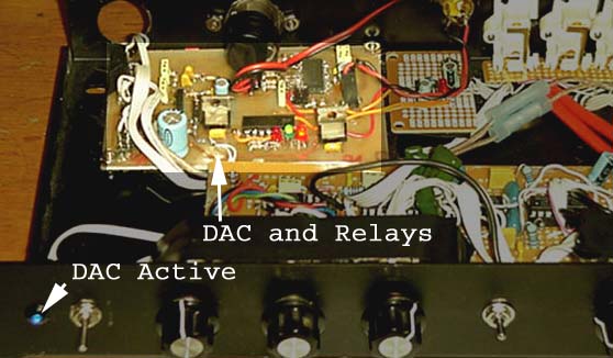
Photo of DAC
Unit
The photo above shows the author's unit, with a couple of pointers to things of interest. The entire board is about 75 x 100 millimetres (3" x 4" for the metrically challenged :-)
There will be occasions where the user may want to convert COAX to TTL signal levels. The circuit in Figure 5 will accomplish this conversion, and can use the unused gates in U4 (a hex inverter). This is as simple as it can get, and the circuit will not work correctly (if at all) if the levels are too low. Impedance matching is quite accurate, and it will load the transmitter to almost exactly +/-0.25V.
Figure 5 - COAX to TTL
Converter
Just for completeness, here is a circuit for TTL to COAX conversion. Again, standard 74HC04 inverter gates are used (the same ones as Figure 5, in fact). The resistors at the output reduce the level to the required levels and provide the correct impedance of 75 ohms.
Figure 6 - TTL to COAX
converter
The actual output impedance is 72 ohms, and if you really wanted to, you could add a 3.3 ohm resistor at the output. The error is too small to worry about though. The resistors are standard E24 values, so should not be too painful to acquire.
Randy is now able to supply the ICs for this project in single units.
For details, see audiochips.net
Note that the TTL to COAX and vice versa schematics are based on material I located on the Web (and reproduced here by permission), from the web site http://www.andrewkilpatrick.org/projects/spdif/ and the appropriate credit for the idea is due to Andrew Kilpatrick (the author of that page). This is fairly standard CMOS circuitry, and similar techniques have been used by myself and others for many years (although for completely different purposes).
The schematics shown in Figures 5
and 6 have been simulated to verify correct operation, but were not tested in
"real life". They should work perfectly, based on the simulator
results.
| Copyright Notice. This
article, including but not limited to all text and diagrams, is the
intellectual property of Randy McAnally and Rod Elliott, and is
Copyright |